Description
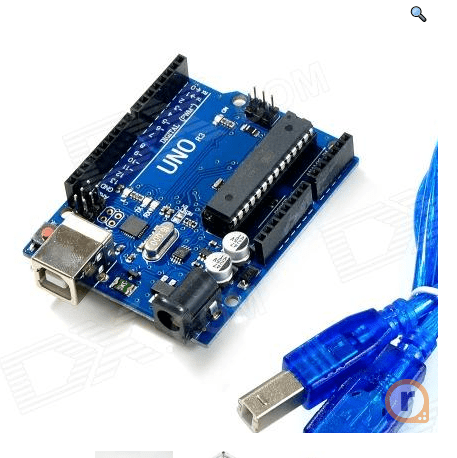
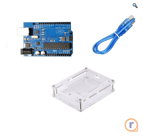
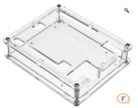
This Uno R3 compatible board is a great way to get started with Arduino. It’s fully compatible with the Arduino Uno R3 and comes with a USB cable and a transparent acrylic case to protect your board. Perfect for beginners and experienced makers alike, this kit provides everything you need to start experimenting with electronics and coding. The Uno R3 is based on the ATmega328 microcontroller and features 14 digital input/output pins (6 of which can be used as PWM outputs), 6 analog inputs, a 16 MHz ceramic resonator, a USB connection, a power jack, an ICSP header, and a reset button. The transparent acrylic case not only offers protection but also allows you to see the components of your board.
This is Uno R3 compatible with Arduino + Cable + Transparent acrylic case for Uno R3. A basic Arduino kit with all the components included eliminating the time our customers for finding and buying Arduino ant its basic accessories.
The Uno R3 Arduino without Cable is a micro-controller board base on the ATmega328 (datasheet). It has 14 digital input/output pins (of which 6 can be used as PWM outputs); 6 analog inputs, a 16 MHz ceramic resonator, a USB connection, a power jack, an ICSP header, and a reset button.
It contains everything need to support the microcontroller; simply connect it to a computer with a USB cable or power it with an AC-to-DC adapter or battery to get started.
“Uno” means one in Italian and is the name to mark the upcoming release of Arduino 1.0. The Uno and version 1.0 will be the reference versions of Arduino, moving forward. The Uno is the latest in a series of USB Arduino boards and the reference model for the Arduino platform; for a comparison with previous versions, see the index of Arduino boards.
The pack includes good quality USB-A to USB-B type Arduino connecting cable and also a strong Transparent Acrylic Case for keeping your Arduino safe. It is a Plug-N-Play provision. Let’s start coding now!!!!
Note: The Uno R3 reference design can use an Atmega8, 168, or 328, Current models use an ATmega328, but an Atmega8 is shown in the schematic for reference. The pin configuration is identical on all three processors.
Power
The Uno R3 can be powered via the USB connection or with an external power supply. The power source is selected automatically.
External (non-USB) power can come either from an AC-to-DC adapter (wall-wart) or battery. The adapter can be connected by plugging a 2.1mm center-positive plug into the board’s power jack. Leads from a battery can be inserted in the Gnd and Vin pin headers of the POWER connector.
The board can operate on an external supply of 6 to 20 volts. If supplied with less than 7V, however, the 5V pin may supply less than five volts and the board may be unstable. If using more than 12V, the voltage regulator may overheat and damage the board. The recommended range is 7 to 12 volts.
The power pins are as follows :
- VIN. The input voltage to the Arduino board when it’s using an external power source (as opposed to 5 volts from the USB connection or another regulated power source). You can supply voltage through this pin, or, if supplying voltage via the power jack, access it through this pin.
- 5V.This pin outputs a regulated 5V from the regulator on the board. The board can be supplied with power either from the DC power jack (7 – 12V), the USB connector (5V), or the VIN pin of the board (7-12V). Supplying voltage via the 5V or 3.3V pins bypasses the regulator, and can damage your board. We don’t advise it.
- 3V3. A 3.3 volt supply generated by the onboard regulator. The maximum current draw is 50 mA.
- GND. Ground pins.
- IOREF. This pin on the Arduino board provides the voltage reference with which the microcontroller operates. A properly configured shield can read the IOREF pin voltage and select the appropriate power source or enable voltage translators on the outputs for working with the 5V or 3.3V.
Memory
The ATmega328 has 32 KB (with 0.5 KB used for the bootloader). It also has 2 KB of SRAM and 1 KB of EEPROM (which can be read and written with the EEPROM library).
Input and Output
Each of the 14 digital pins on the Uno can be used as an input or output, using pinMode(), digitalWrite(), and digitalRead() functions. They operate at 5 volts. Each pin can provide or receive a maximum of 40 mA and has an internal pull-up resistor (disconnected by default) of 20-50 kOhms. In addition, some pins have specialized functions:
- Serial: 0 (RX) and 1 (TX). Used to receive (RX) and transmit (TX) TTL serial data. These pins are connected to the corresponding pins of the ATmega8U2 USB-to-TTL Serial chip.
- External Interrupts 2 and 3. These pins can be configured to trigger an interrupt on a low value, a rising or falling edge, or a change in value. See the attachInterrupt() function for details.
- PWM: 3, 5, 6, 9, 10, and 11. Provide 8-bit PWM output with the analogWrite() function.
- SPI: 10 (SS), 11 (MOSI), 12 (MISO), 13 (SCK). These pins support SPI communication using the SPI library.
- LED: 13. There is a built-in LED connected to digital pin 13. When the pin is HIGH value, the LED is on, when the pin is LOW, it’s off.
The Uno R3 has 6 analog inputs, labeled A0 through A5, each of which provides 10 bits of resolution (i.e. 1024 different values). By default, they measure from ground to 5 volts, though is it possible to change the upper end of their range using the AREF pin and the analogReference() function. Additionally, some pins have specialized functionality:
- TWI: A4 or SDA pin and A5 or SCL pin. Support TWI communication using the Wire library.
There are a couple of other pins on the board:
- AREF. A reference voltage for the analog inputs. Used with analogReference().
- Reset. Bring this line LOW to reset the microcontroller. Typically used to add a reset button to shields which block the one on the board.
See also the mapping between Arduino pins and ATmega328 ports. The mapping for the Atmega8, 168, and 328 is identical.
Communication
The Uno R3 has a number of facilities for communicating with a computer, another Arduino, or other microcontrollers. The ATmega328 provides UART TTL (5V) serial communication, which is available on digital pins 0 (RX) and 1 (TX). An ATmega16U2 on the board channels this serial communication over USB and appears as a virtual com port to software on the computer. The ’16U2 firmware uses the standard USB COM drivers, and no external driver is needed. However, on Windows, a .inf file is required. The Arduino software includes a serial monitor which allows simple textual data to be sent to and from the Arduino board. The RX and TX LEDs on the board will flash when data is being transmitted via the USB-to-serial chip and USB connection to the computer (but not for serial communication on pins 0 and 1).
A SoftwareSerial library allows for serial communication on any of the Uno’s digital pins.
The ATmega328 also supports I2C (TWI) and SPI communication. The Uno R3 software includes a Wire library to simplify use of the I2C bus; see the documentation for details. For SPI communication, use the SPI library.
Programming
The Uno R3 can be a program with the Arduino software (download). Select “Arduino Uno from the Tools > Board menu (according to the microcontroller on your board). For details, see the reference and tutorials.
The ATmega328 on the Uno R3 comes pre-burn with a bootloader that allows you to upload new code to it without the use of an external hardware programmer. It communicates using the original STK500 protocol (reference, C header files).
You can also bypass the bootloader and program the microcontroller through the ICSP (In-Circuit Serial Programming) header; see these instructions for details.
The ATmega16U2 (or 8U2 in the rev1 and rev2 boards) firmware source code is available. The ATmega16U2/8U2 is load with a DFU bootloader, which can be activated by:
- On Rev1 boards: connecting the solder jumper on the back of the board (near the map of Italy) and then resetting the 8U2.
- On Rev2 or later boards:


Reviews
There are no reviews yet.